Wheels are the only contact point with the ground. They convey loads from your vehicle onto the ground and from the ground into your vehicle. So they are of a paramount importance when it comes to finding or using a bike. Along the last few millennia a wide variety wheel types have came to use ranging from solid wheels to spoke wheels and including as funny items as the square wheels.
The most common bike wheel is by far the wire spoked wheel, however it is not the only wheel available to bike users both currently and in the century and a half they have been around us. Since they are the most common we will focus on them, so we will not discuss 3 spoke magnesium wheels or carbon dish wheels since they work in a completely different way.
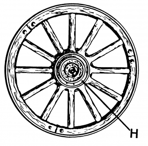
Wire wheels work as tensegrity structures instead of compression ones as most wheels do. The first non bike wheel coming to many people’s mind might be a cart wheel. They work by compressing their spokes (or their bodies in case of being a disc wheel) so their spokes have to be able to withstand high compressive loads. This makes them heavy and gives them a high rotational inertia.

i= \int \rho r dr
and then makes it difficult for the wheel to change its rotational speed and hence its angular momentum. Since
L= \Iota \omega
and then makes it difficult not only to brake and to accelerate the bike, but also to steer it since ![]() is a (pseudo) vector and changing its direction will require the use of energy by applying an specific torque (
is a (pseudo) vector and changing its direction will require the use of energy by applying an specific torque (![]() ).
).
Wire wheels have an extra advantage. They provide some degree of shock absorption by the very design. Wire wheels are built around spokes that act as pre-stressed springs the tensions of which varies according to both the load and the position of the wheel. Thence, we shall describe the particular arrangement of spokes (springs) around a hub and the rim which could be considered another spring however, a much harder one. In real life further cushioning is almost always provided by means of pneumatic rubber tyres where both the rubber compound and the air provide elastic shock absorption.
Each spring represents one spoke.
Spoke A has no tension applied yet.
Tension it’s been applied on spoke C by the force ![]() causing an elongation
causing an elongation ![]() .
.
Meanwhile, an additional external force ![]() — with opposite way to
— with opposite way to ![]() — has been applied on spoke B causing an elongation
— has been applied on spoke B causing an elongation ![]() .
.
In case ![]() spoke would become under compression causing its failure. That is why spoke tension is of a paramount importance and every single spoke shall always be under pure tension.
spoke would become under compression causing its failure. That is why spoke tension is of a paramount importance and every single spoke shall always be under pure tension.
Sadly all the above does not came without a price. This price is that every single spoke shall always be under pure tension (and have not other stress but tension) however much strange might it seem. Here human ingenuity has manged to overcame this shortcoming by using highly imaginative designs.
Wheels are intended to be in equilibrium so the total force on them shall be zero, otherwise the wheel would be changing its shape on its own, which is different form the real world wheel we will try to describe.
The structure of a wheel is defined by the stresses it is intended to withstand. This makes it no different from any other piece of engineering. The forthcoming paragraph will focus on different possible situations both ¡¡drought!! form real life and for their ability to give better understanding of the way a wire wheel is intended to work.
In case a wheel only had to withstand a perfectly radial load, every force should follow a purely radial direction, so every single spoke would have to be both radial and contained within the same plane as the rolling surface (the one one which normal vector is parallel to the wheels rotation axle).
Were we to include lateral forces as they might be found when cornering, lateral stresses would appear. Then we would need to balance them somehow since we want our wheel to work under tension.
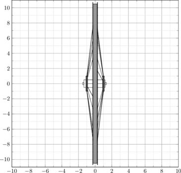
28 spokes no cross lacing pattern front wheel.
(Front view)
The most straightforward way of doing so would be having two sets of spokes coming at an angle. As a result we will have two different sets of spokes each of them coming from a different side of the plane containing the rim. As a result each set will be attached to the hub at a specific distance from the center of the wheel. We will call the angle within the two sets ![]() and hence the distance to the middle of the hub shall be:
and hence the distance to the middle of the hub shall be:
\frac{r}{\sin(\alpha)}
28 spokes no cross lacing pattern front wheel.
(Side view)
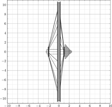
In case both sets were attached at different distances from the middle point, then we would have two angles ![]() and
and ![]() in any case every force shall result into
in any case every force shall result into ![]() as we will see.
as we will see.

28 spokes no cross lacing pattern rear wheel.
(Side view)
In this case we have two directions. The radial one and the normal one (no forces in the rolling direction are taking into account yet).
The radial direction will just have a force and this force shall be cancelled by the elastic deformation of the rim so any calculation on that side would require a deep knowledge of the particular rim. Since the aim of this text is just giving the reader a simple introduction into wire wheels statics we will just decompose the force for every radial spoke and leave the wheel specific details to the reader.
![]() where
where ![]() is the spoke tension and
is the spoke tension and ![]() is the radial component of its force. Please, see the sections where deal with their use and nature in full detail.
is the radial component of its force. Please, see the sections where deal with their use and nature in full detail.
Then the normal forces shall be ![]() .
.
For the wheel not to deform all the forces shall add up to zero, and due to the properties of vector addition in orthogonal euclidean spaces (As the one we use as a model for our environment) each component should add zero independently so:
\sum f_n=0 \land \sum f_ r =0
